
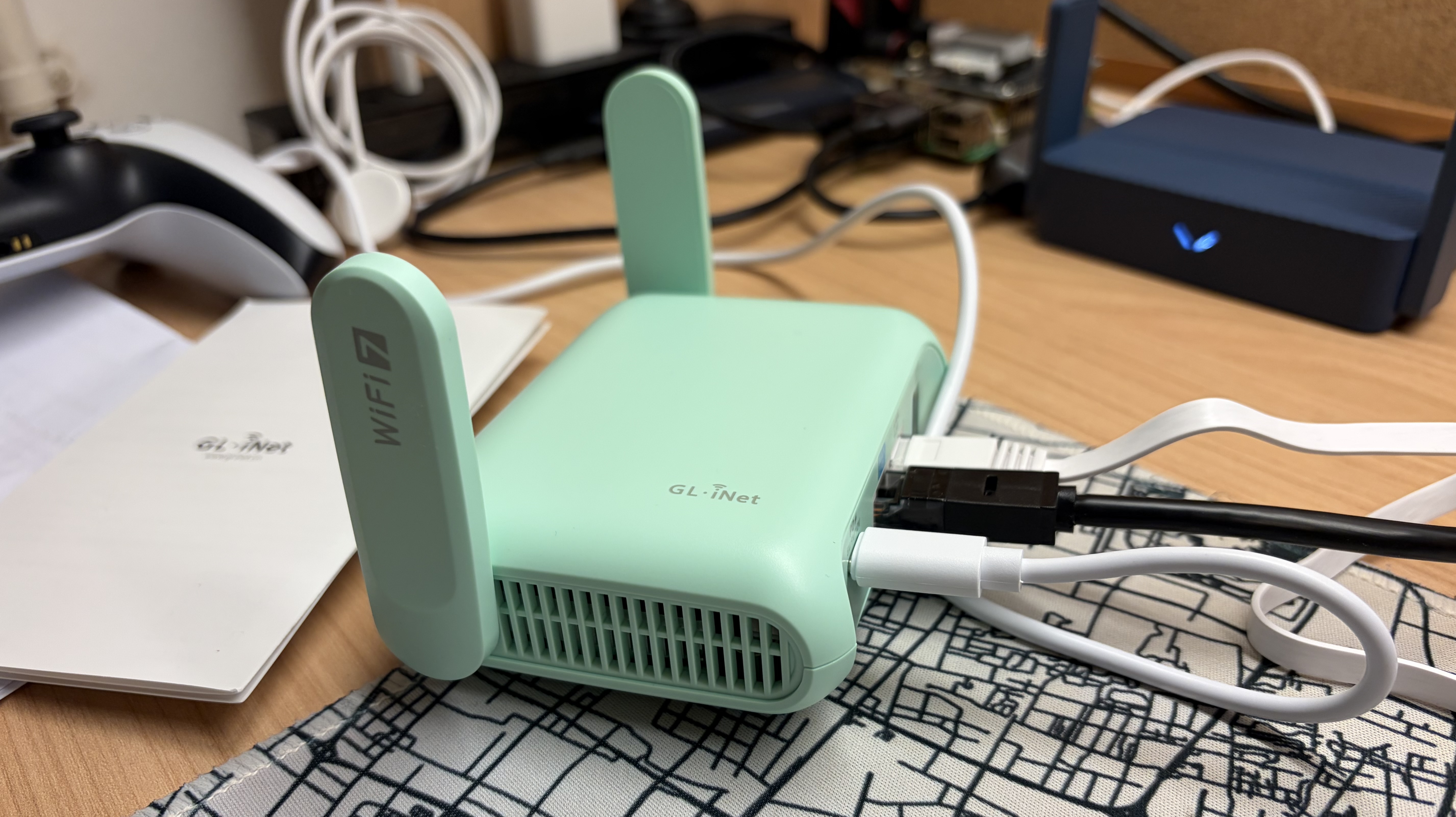
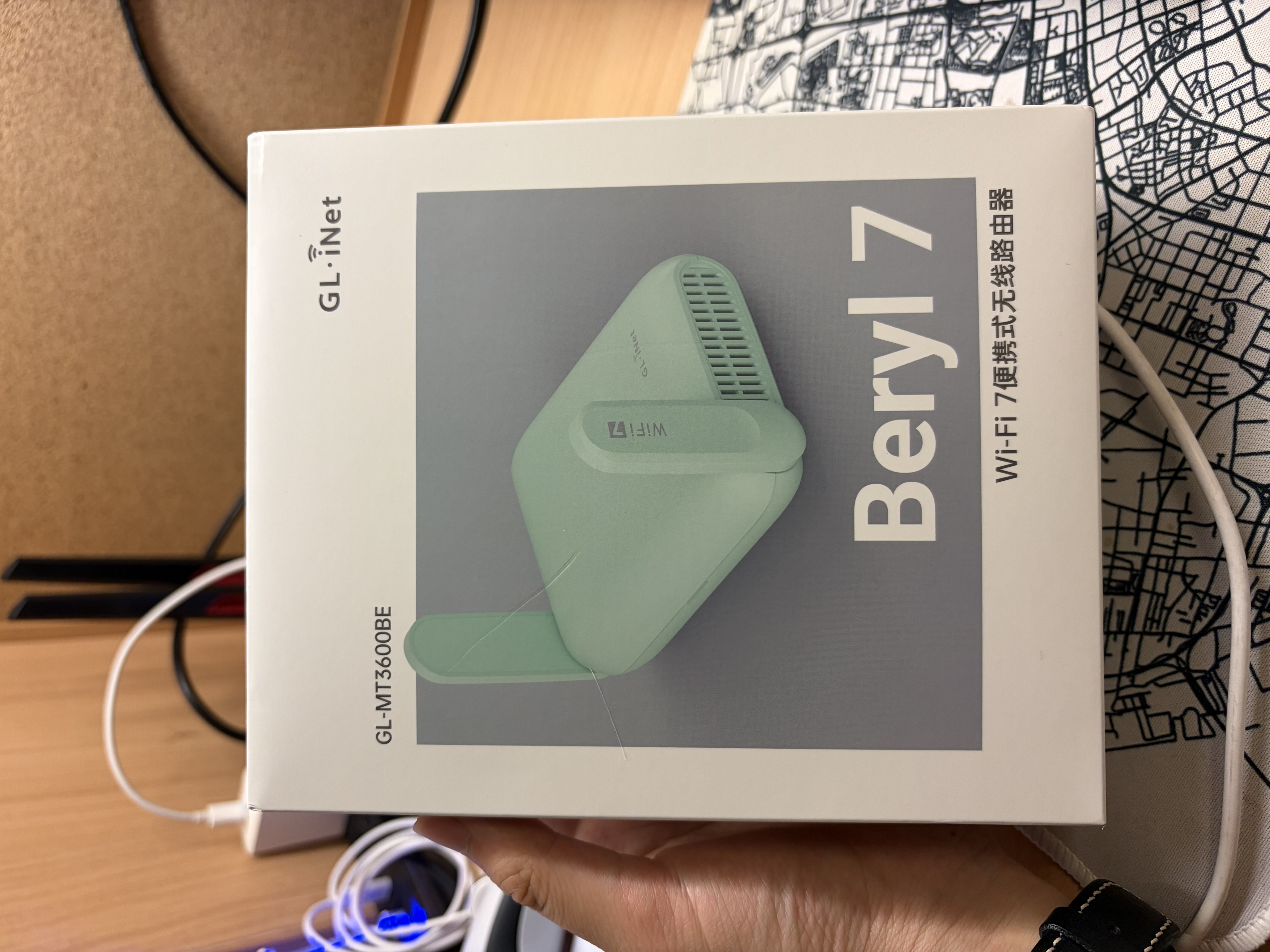
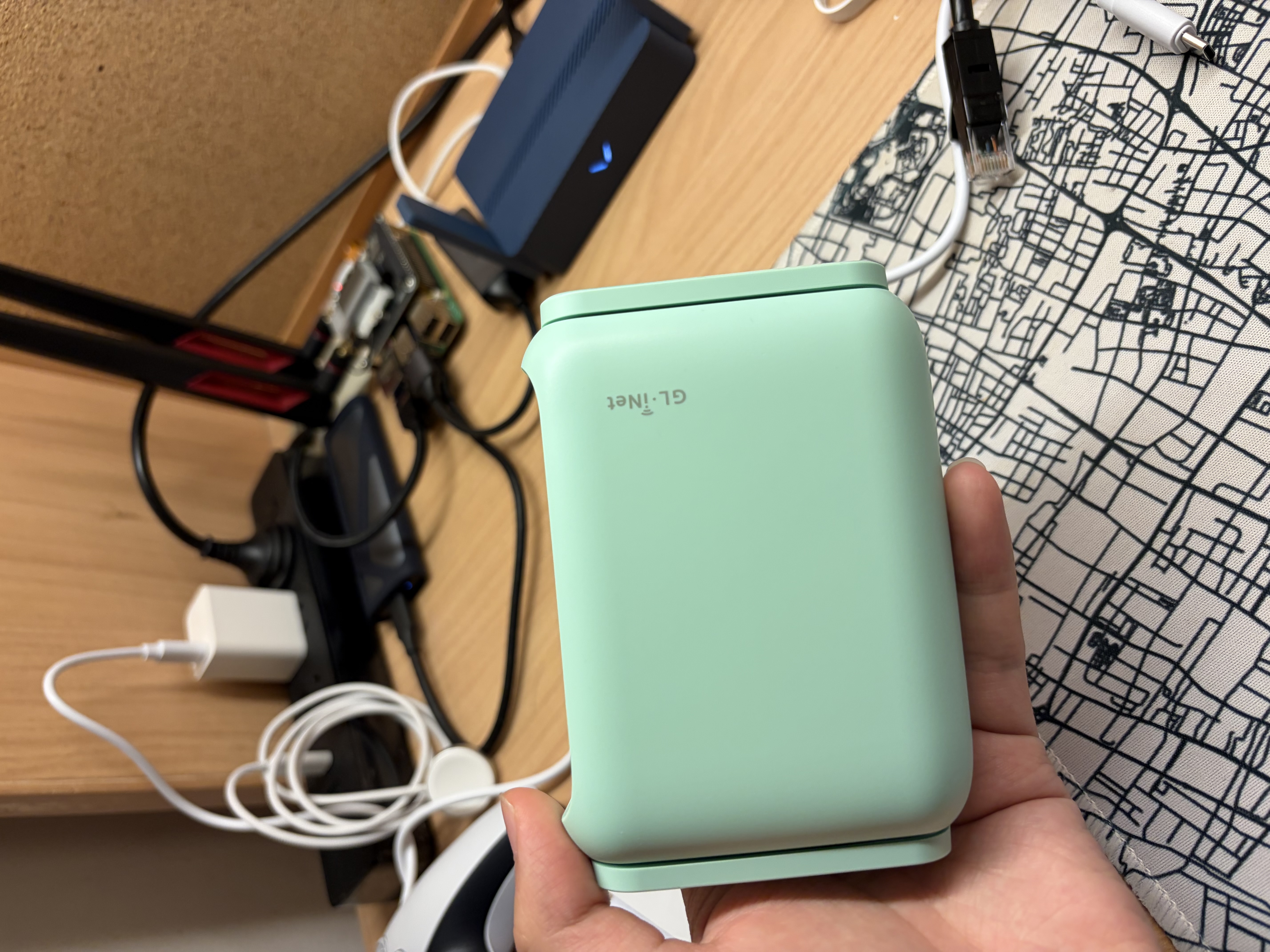
Shown above is a GL.iNet mt3600be router, used in this blog post for demonstration. It uses an OpenWrt- based system, providing excellent flexibility. It will be used as a powerful MLO (Wi-Fi 7) Access Point.
As you can see, this is a CN version of a GL.iNet router. Features including VPN and AdGuard Home are blocked (hidden). For Wi-Fi 7 MLO, 6 GHz bandwidth may also be limited. To achieve the best experience, you can unlock it by replacing the country code in the factory image1. For the global version, you already have most features available.
Table of Contents
What is an AC+AP style network?
An AC+AP network is composed of a central Access Controller and one or more Access Points. It is widely used in enterprise environments for large Wi-Fi coverage and fast roaming. Campus Wi-Fi is a classic example of an AC+AP style network. It can cover an entire campus, and users normally cannot feel the latency when a device switches APs. AC+AP architecture utilizes 802.11k/v/r standards to achieve seamless AP transitions, which is a key advantage.
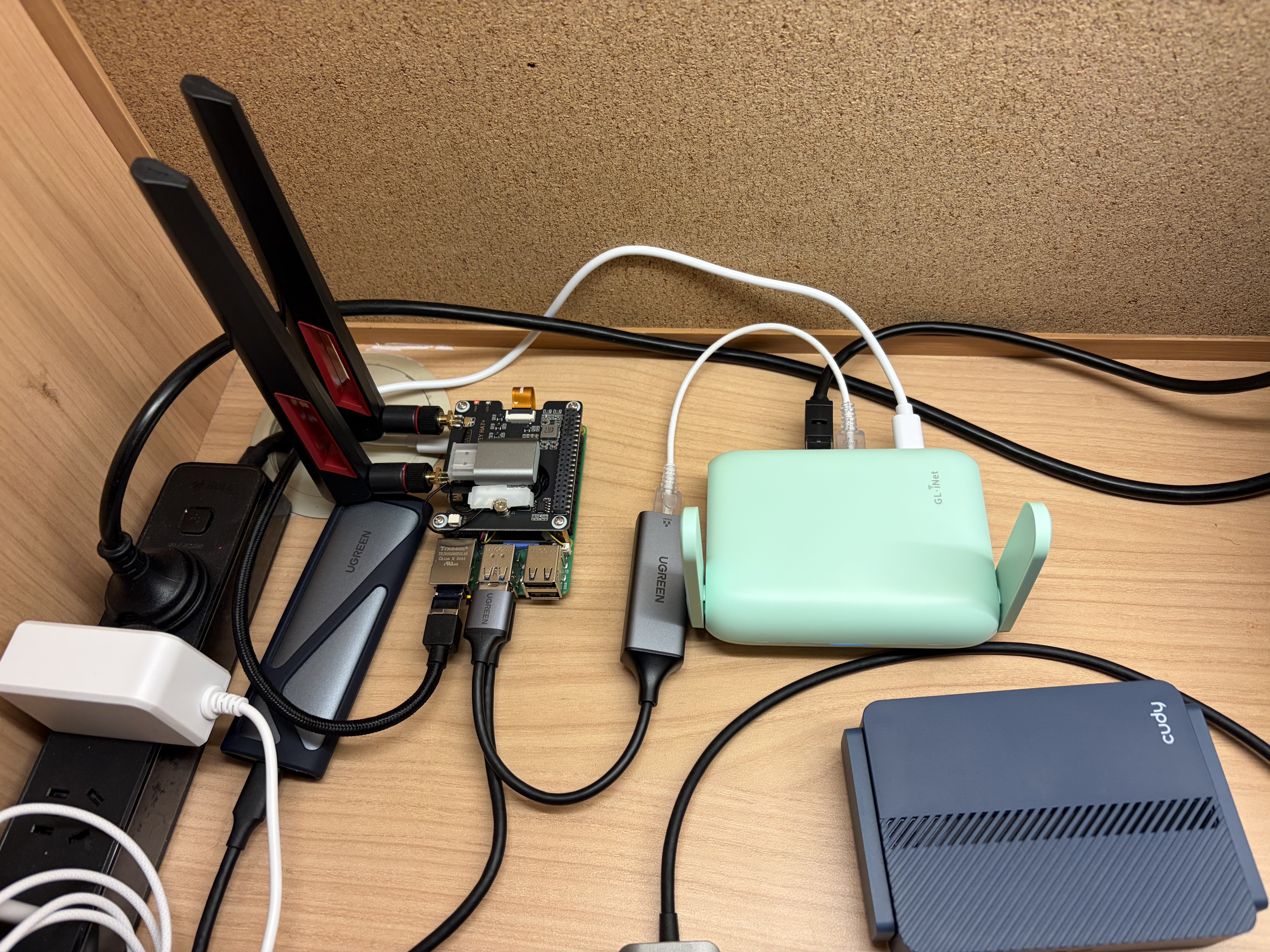
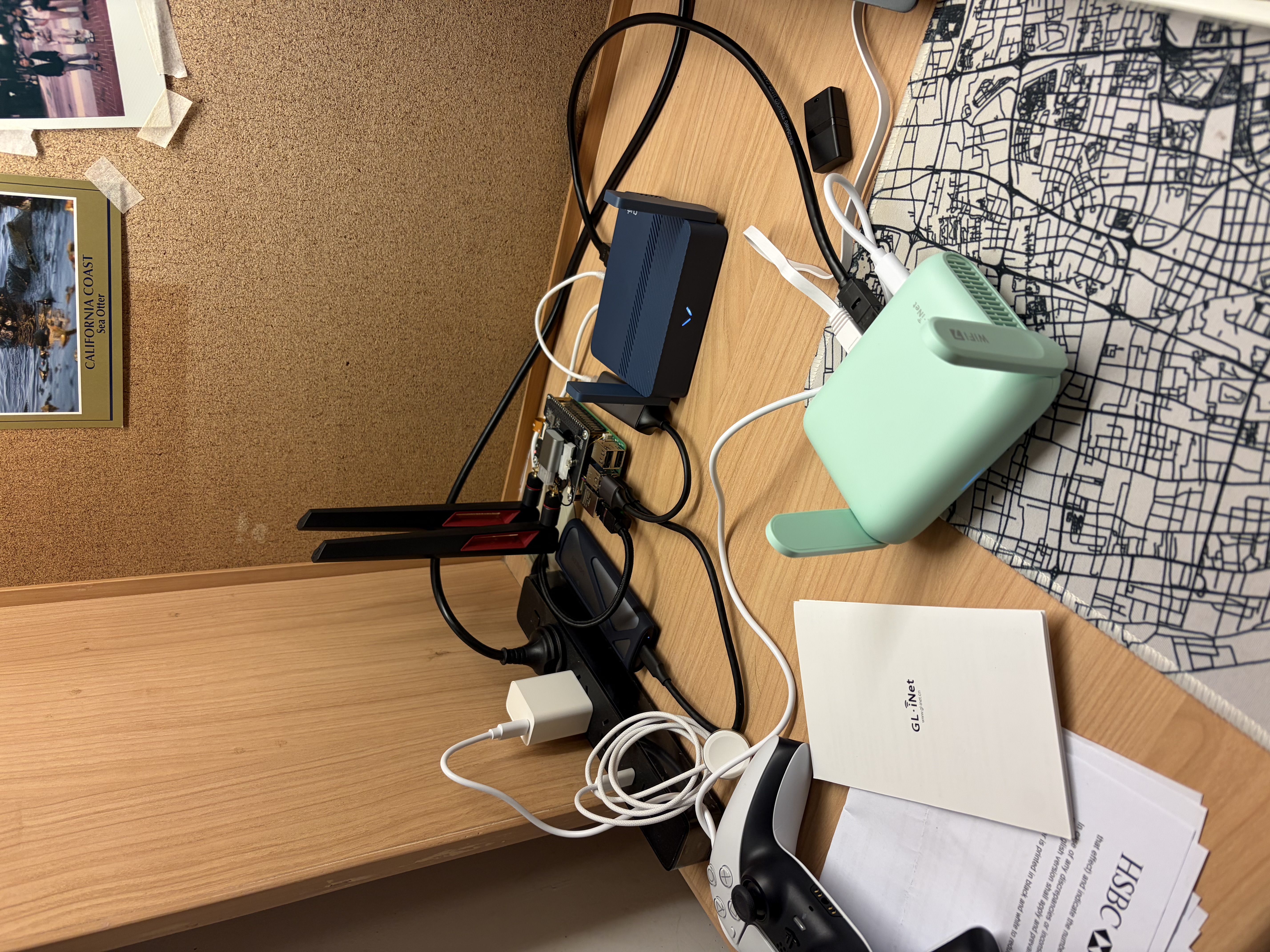
The image above is an illustration of the finished setup. The Raspberry Pi 5 on the left is my AC and gateway. The mt3600be on the right is used as a wireless access point, supporting Wi-Fi 7. The Wi-Fi card, mt7925, on top of the Pi is a secondary AP that I built in this post. This post can be seen as an extension of that earlier blog on how to DIY your own router.
Components of AC+AP network
- AC: a central controller that manages one or more APs. In this setup, the Raspberry Pi also acts as the router/gateway.
- AP: Wireless access point. mt3600be and mt7925 are used.
- PoE Switch: Optional. Use an Ethernet cable for power and data for a simpler setup. The switch ensures all AC and AP devices are in one subnet.
- Main router: Used to access WAN. A Raspberry Pi is used.
Difference to mesh architecture?
An AC+AP (Access Controller + Access Points) network is a centralized Wi-Fi architecture where multiple APs are managed by a single controller that handles configuration, channel planning, and roaming, typically with all APs connected via wired Ethernet cable. In contrast, a mesh network is distributed: each node acts as both an AP and a relay, forwarding traffic over wireless links to other nodes without requiring a central controller. The key difference is therefore centralized control with wired connection (AC+AP) versus distributed forwarding with wireless connection (mesh). As a result, AC+AP systems usually provide more stable performance and predictable latency, while mesh networks offer easier deployment but can suffer reduced throughput due to multi-hop wireless links.
AC+AP is designed to scale larger, targeted for enterprise scenarios, while mesh is targeted for smaller/home networks.
Access Controller & Main Router configuration
Now let’s dive into configuration. On OpenWrt, when you inspect interfaces,
you can find one called br-lan; it is a virtual switch. On the AC (Raspberry Pi), you need
a virtual switch as well, to put multiple network interfaces into one LAN.
2: eth0: <BROADCAST,MULTICAST,UP,LOWER_UP> mtu 1500 qdisc fq_codel state UP group default qlen 1000
    link/ether 2c:cf:67:f5:96:bd brd ff:ff:ff:ff:ff:ff
    inet 143.89.92.189/23 brd 143.89.93.255 scope global dynamic noprefixroute eth0
       valid_lft 322039sec preferred_lft 322039sec
    inet6 fe80::2ecf:67ff:fef5:96bd/64 scope link noprefixroute
       valid_lft forever preferred_lft forever
3: eth1: <BROADCAST,MULTICAST,UP,LOWER_UP> mtu 1500 qdisc fq_codel master br0 state UP group default qlen 1000
    link/ether 9c:69:d3:75:af:fe brd ff:ff:ff:ff:ff:ff
    inet6 fe80::9e69:d3ff:fe75:affe/64 scope link proto kernel_ll
       valid_lft forever preferred_lft forever
5: wlan1: <BROADCAST,MULTICAST,UP,LOWER_UP> mtu 1500 qdisc noqueue master br0 state UP group default qlen 1000
    link/ether 84:9e:56:9c:71:a5 brd ff:ff:ff:ff:ff:ff
    inet6 fe80::869e:56ff:fe9c:71a5/64 scope link proto kernel_ll
       valid_lft forever preferred_lft forever
6: br0: <BROADCAST,MULTICAST,UP,LOWER_UP> mtu 1500 qdisc noqueue state UP group default qlen 1000
    link/ether 84:9e:56:9c:71:a5 brd ff:ff:ff:ff:ff:ff
    inet 192.168.205.1/24 scope global br0
       valid_lft forever preferred_lft forever
Above are the network interfaces used on my AC. br0 is the virtual switch and holds my network subnet IP
address: 192.168.205.1/24. wlan1 is the mt7925 interface and provides a 5 GHz radio. eth1 is
my USB-to-Ethernet adapter, connected externally to my GL.iNet mt3600be AP. eth0 is the WAN interface; all
traffic will be masqueraded and exit through it.
Set up bridge on startup
To maintain a persistent bridge even after reboot, the best approach is to use a systemd service.
Create a /usr/local/sbin/setup-br0.sh shell script that runs on startup.
#!/usr/bin/env bash
set -euo pipefail

BR=br0
LAN_IP=192.168.205.1/24

# Create bridge if missing
if ! ip link show "$BR" >/dev/null 2>&1; then
    ip link add name "$BR" type bridge
fi

# Make sure bridge is up and owns the LAN IP
ip link set dev "$BR" up
ip link set dev "$BR" type bridge stp_state 0 || true

ip addr flush dev "$BR" 2>/dev/null || true
ip addr add "$LAN_IP" dev "$BR"

# Add eth1 only if it exists
# eth1 is usb ethernet adaptor
if ip link show eth1 >/dev/null 2>&1; then
    ip addr flush dev eth1 2>/dev/null || true
    ip link set dev eth1 nomaster 2>/dev/null || true
    ip link set dev eth1 master "$BR"
    ip link set dev eth1 up
fi

# We don't set wlan1 master to br0 here is because
# hostapd will do the bridge configuration
# leave it to hostapd
You may need to modify the script based on your actual setup. For a Raspberry Pi 5 with a USB Ethernet adapter, you can use the script as is.
Create a systemd unit: /etc/systemd/system/setup-br0.service
[Unit]
Description=Create br0 bridge and attach eth1
Before=hostapd.service
After=NetworkManager.service
Requires=NetworkManager.service

[Service]
Type=oneshot
ExecStart=/usr/local/sbin/setup-br0.sh
RemainAfterExit=yes

[Install]
WantedBy=multi-user.target
Then run sudo systemctl daemon-reload && sudo systemctl enable setup-br0; this will make the script
execute at startup.
After reboot or direct execution of the script, you can verify it with bridge link show. All network
interfaces that you want to place in the same LAN should share the same master bridge. In my case, as shown
below, wlan1 and eth1 both have master br0.
3: eth1: <BROADCAST,MULTICAST,UP,LOWER_UP> mtu 1500 master br0 state forwarding priority 32 cost 5
5: wlan1: <BROADCAST,MULTICAST,UP,LOWER_UP> mtu 1500 master br0 state forwarding priority 32 cost 100
For the wlan1 interface, you don’t manually assign it to br0. Put that in the hostapd config file, and hostapd will configure it for you.
Configure routing (firewall)
Now that your bridge is configured, it is time to configure routing rules and access controls. I use nftables as the firewall, which gives more granular control than ufw or firewall-cmd. nftables is the default firewall in modern Linux operating systems, offering better usability than iptables.
#!/usr/sbin/nft -f

# add table ensures the table exists before flush
# Do not use flush ruleset, scope is too big
# And will modify iptables-nft rules
add table inet filter
flush table inet filter

table inet filter {
    chain input {
        type filter hook input priority 0; policy drop;

        iifname "lo" accept
        ct state established,related accept

        # DNS / DHCP / UPnP
        iifname { "br0", "wlan1", "eth1" } udp dport { 67, 53 } accept
        iifname { "br0", "wlan1", "eth1" } tcp dport 53 accept

        ip protocol icmp accept
        ip6 nexthdr ipv6-icmp accept
    }

    chain forward {
        type filter hook forward priority 0; policy drop;

        ct state established,related accept

        # Normal routing
        iifname "br0" oifname "eth0" accept

        # LAN, change to your subnet
        ip saddr 192.168.205.0/24 accept

        ip protocol icmp accept
        ip6 nexthdr ipv6-icmp accept
    }

    chain output {
        type filter hook output priority 0; policy accept;
    }

    # ---------- NAT ----------
    chain prerouting {
        type nat hook prerouting priority dstnat; policy accept;
    }

    chain postrouting {
        type nat hook postrouting priority srcnat; policy accept;
        oifname "eth0" ip saddr 192.168.205.0/24 masquerade
    }
}
Above is an example of restricted cone NAT achieved with nftables2,
the most common NAT type. If you are using P2P,
consider using miniupnpd3 or change postrouting last line to
oifname "eth0" ip saddr 192.168.205.0/24 masquerade fully-random, persistent, change source address
field to your LAN address.
What does an AC+AP router need?
- Routing: Covered, use nftables
- DHCP / DNS: use dnsmasq4
- Bridge LAN: Covered, use shell script to manually create and assign
- Radio: use hostapd or add a router as a dummy access point (covered next).
Before you continue, you should finish the first 3 steps, or at least part of step 4. For me, I am using hostapd on wlan15, my MediaTek Wi-Fi card.
Access Point configuration on OpenWrt
Generic OpenWrt
On OpenWrt, to achieve the best roaming speed, 802.11k/v/r standards are required. OpenWrt firmware usually bundles wpad-basic-mbedtls, which does not include support for these standards. We will need to install wpad-openssl for full support.
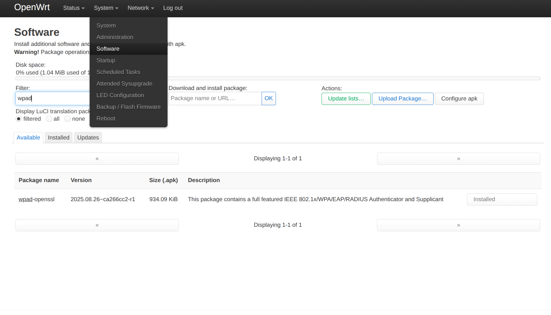
On the latest OpenWrt 25.12 version, use apk add wpad-openssl or go to LuCI6 and install the package
in System->Software, search wpad-openssl, and install it.
Then go to Network->Wireless and configure radio settings.
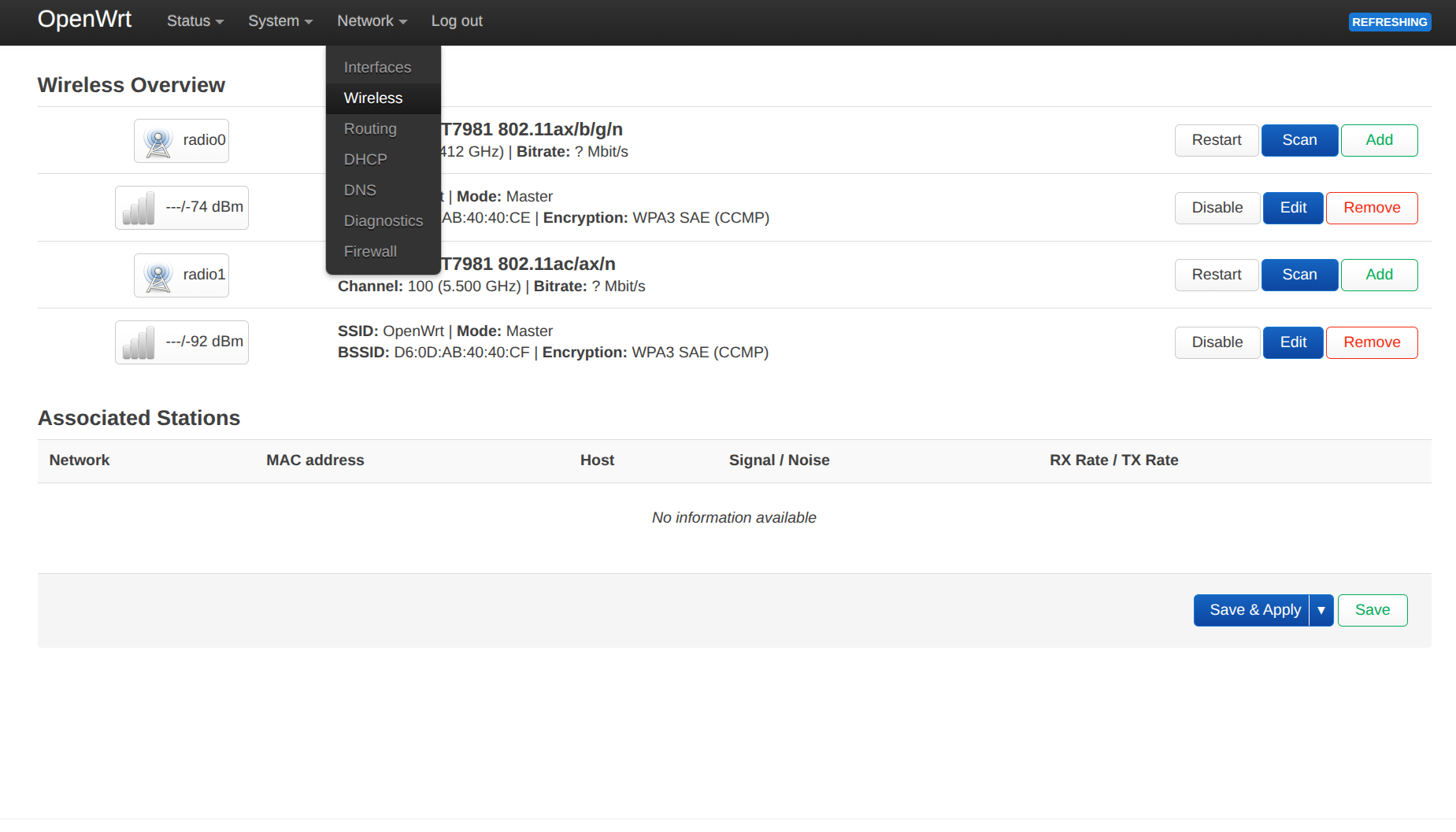
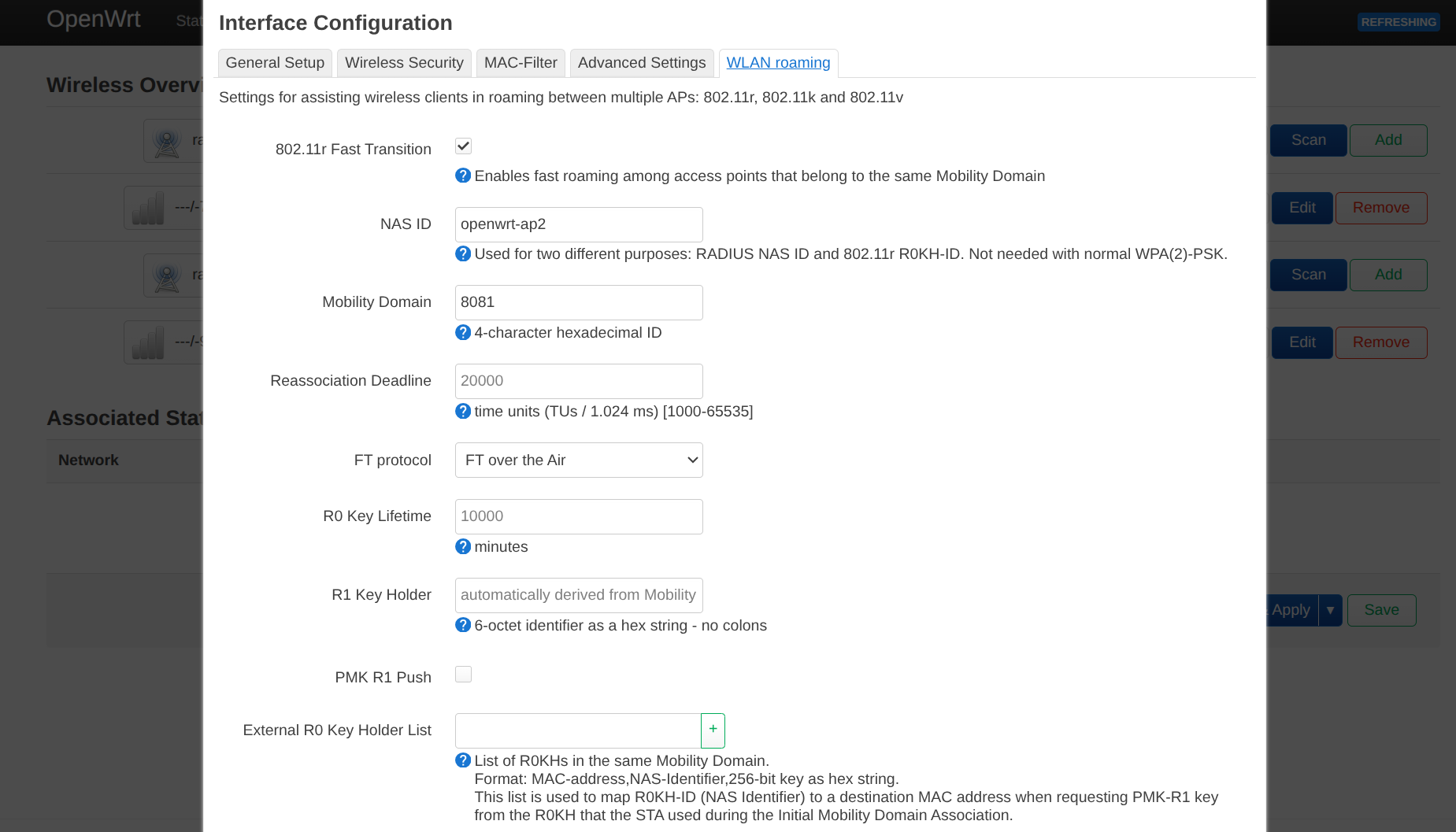
I recommend using interactive configuration instead of UCI because it is easier. On older OpenWrt versions, such as 21 on mt3600be, LuCI does not provide a section to edit roaming configuration, even though it is supported. In that case, UCI is needed.
Lastly, go to Edit radio, configure your Access Point, disable DHCP on br-lan, and set br-lan
to a static IP address.
GL.iNet OpenWrt
In GL.iNet Network mode, you can set OpenWrt to Access Point. It will automatically disable DHCP and request an IP address from the upstream router via DHCP.
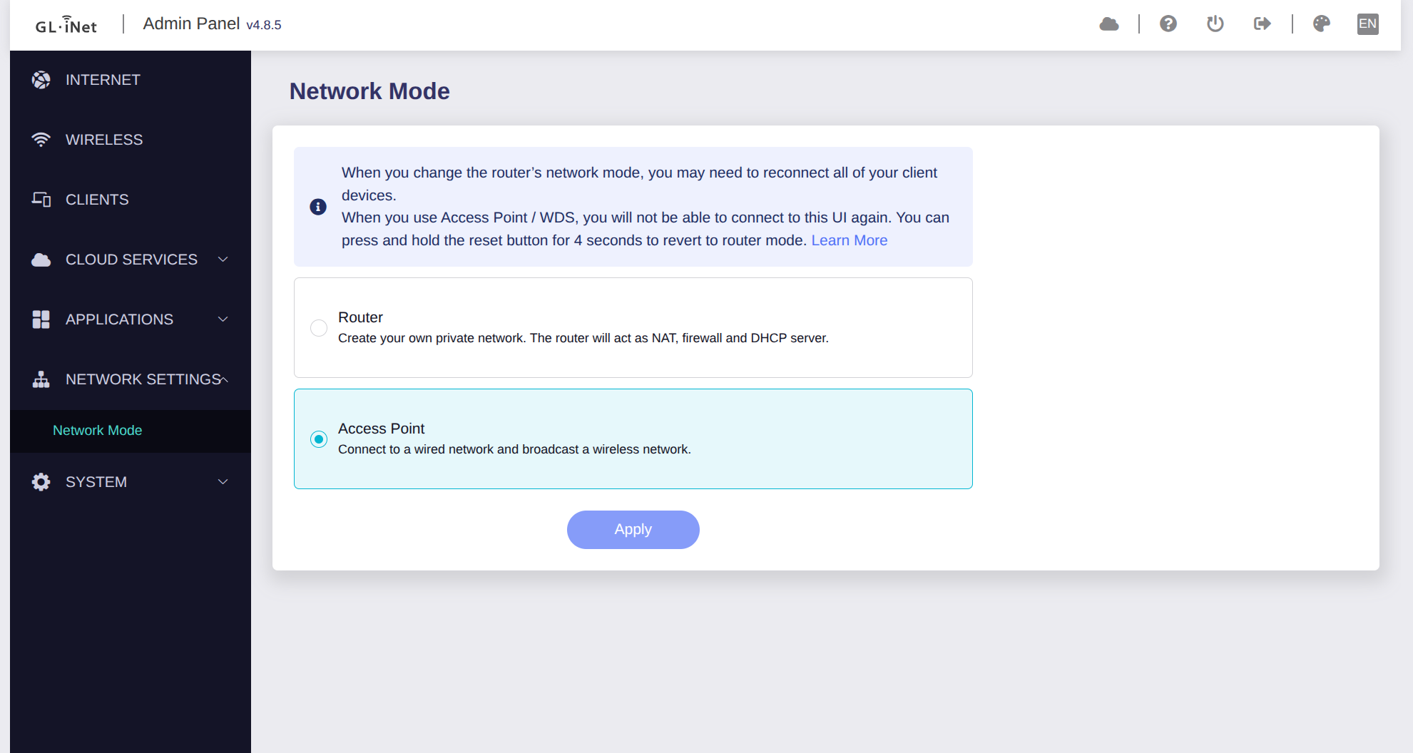
This does not provide your router with a static IP address. When accessing the router admin panel remotely, you’ll need to look up the IP address on the main router. Or use the following:
uci set network.lan.ipaddr='192.168.205.2' # In the same subnet, avoid IP address collision
uci set network.lan.netmask='255.255.255.0'
uci commit network
/etc/init.d/network restart
To enable 802.11k/v/r, use the following:
uci set wireless.lan.ieee80211r='1'
uci set wireless.lan.mobility_domain='4f57'
uci set wireless.lan.ft_over_ds='1'
uci set wireless.lan.ft_psk_generate_local='1'

uci set wireless.lan.bss_transition='1'

uci set wireless.lan.rrm_neighbor_report='1'
uci set wireless.lan.rrm_beacon_report='1'

uci commit wireless
wifi reload
After this, your GL.iNet router will be a powerful access point.
Useful Tips
- Use an Ethernet cable to connect to your router before configuring, in case you lose access midway.
- When configuring the router IP address, your gateway IP address will change, for example from
192.168.8.1to192.168.205.*. So your admin panel will not receive a response at the old address; go to the new IP address to access the admin panel.
For the generic OpenWrt demo, I used a Cudy TR3000 (256 MB version), a Wi-Fi 6 router with an mt7981 chipset. Flashing OpenWrt is very straightforward, and OpenWrt has official support7. This is a decent OpenWrt starter device.
REFERENCES:
Footnotes
-
How to find “CN” string and replace to “US” for GL.iNet mt3600be: https://www.reddit.com/r/GlInet/comments/1qfeva7/guide_region_unlock_glmt3600be_beryl_7_cn_to ↩
-
nftables NAT documentation: https://wiki.nftables.org/wiki-nftables/index.php/Performing_Network_Address_Translation_(NAT)#Masquerading ↩
-
OpenWrt configure upnpd: https://openwrt.org/docs/guide-user/firewall/upnp/miniupnpd ↩
-
Dnsmasq configuration tutorial on Fedora: https://docs.fedoraproject.org/en-US/fedora-server/administration/dnsmasq/ ↩
-
Zihao Fu, configuring mt7925 on Raspberry Pi: https://zihaofu245.me/blog/2026-3-05-pi-router/#Hostapd ↩
-
LuCI documentation: https://openwrt.github.io/luci/jsapi/ ↩
-
Cudy TR3000 OpenWrt documentation: https://openwrt.org/toh/cudy/tr3000 ↩